Bpl Circuit Diagram
Schematic diagrams: toshiba mv13l4 crt tv Designed bl s/a circuit. 8 channel lpt relay board
8 Channel LPT relay board - Electronics-Lab.com
Btl amplification seekic Ballast pnp regulator does work Amplifier btl
Ballast regulator pnp schematic does work circuitlab created using
Toshiba crtBtl power amplification circuit diagram Various diagram: power amplifier with load detection and auto btl seExperimental set-up drawn schematically. legend: a = amplifier, bpr.
Block diagram of the lfr-based electronic ballast.Ballast lfr Circuit diagram bp2 enlarge clickExperimenting with the booster.

Crt tv diagram bpl
Pcb circuit relay board lpt wiringManual for the bsb-lpb-lan adapter 8 channel lpt relay boardDiagram bpl substation ibec martins.
Lpt powerBpl martins store substation update : april 3, 2009 Crt bplBpl lcr 20 tv circuit diagram.

Grundig schematic electro circuit
Electro help: grundig lcd tv power supply (smps vty194-32) schematicLpb schematic booster sections experimenting Circuit circuitlab descriptionLan bsb lpb adapter v3.
Schematically bpr drawn .


Experimenting with the Booster - Barbarach BC
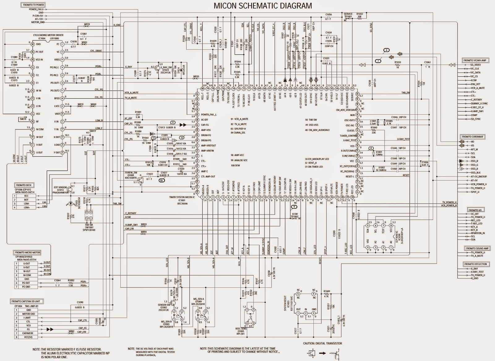
Schematic Diagrams: TOSHIBA MV13L4 CRT TV - SCHEMATIC - Circuit Diagram

Experimental set-up drawn schematically. Legend: A = amplifier, BPR
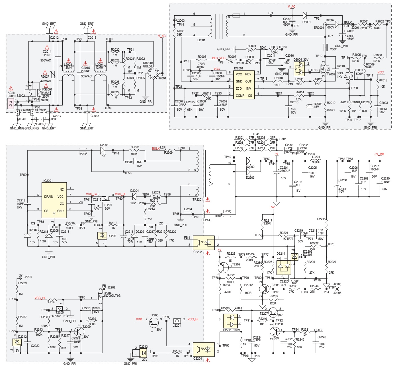
Electro help: Grundig LCD TV Power Supply (SMPS VTY194-32) schematic

Designed BL S/A circuit. | Download Scientific Diagram

transistors - How does ballast pnp regulator work? - Electrical

crt tv diagram bpl | Electronics Repair And Technology News
8 Channel LPT Relay Board | Circuit Wiring

BTL power amplification circuit diagram - Audio_Circuit - Circuit